How to Modify your Atari 2600 Jr.
 Composite
connections will give you better audio and video signals and allow you
to throw away that old TV switchbox or coaxial/RCA converter. These plans
are for the Atari 2600 Jr, other models are slightly different. If you
have better plans (or plans for other models), especially with pictures
or diagrams, please contact us.
Composite
connections will give you better audio and video signals and allow you
to throw away that old TV switchbox or coaxial/RCA converter. These plans
are for the Atari 2600 Jr, other models are slightly different. If you
have better plans (or plans for other models), especially with pictures
or diagrams, please contact us.
Disclaimer: These plans are only for educational purposes.
We are not responsible for any damage you might do to your system. We
recommend you read the entire file before beginning.
Materials Required (you can get it all at Radio Shack for about $20):
- Phillips screwdriver
- Soldering Iron
- Small piece of wire
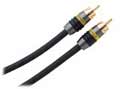
- Two RCA audio/video cables (like the picture)
- Small pair of needle-nose pliers
Atari 2600 Jr.
- Be sure your console is unplugged, and remove the five screws on the
underside of the case.
- Remove the top and bottom plastic case halves. When removing the top
piece , carefully pull out the ribbon cable that connects it to the main
board.
- Turn the board over so the the metal shield is facing away from you,
and you will see some small clasps on the edge of the shield that hold
it in place. Straighten these with your pliers and you can then remove
2 large shields (one on the bottom of unit, one on the top). The small
shield remaining (on top) covers the RF modulator.
- Orient the exposed board into the position that it would normally be
in. The On/Off switch should be near top left.
- Look in the lower right hand area of the top side (front) of the board.
You will see a setup that resembles the schematic below.
                              __________________
TOPSIDE OF THE BOARD,        |                  |
LOWER RIGHTHAND CORNER       |O      RF         |
                             |    MODULATOR     |
                             |                  |
                             |__________________|

                                        ------ TP5 (Luma)
                                        |
                             _____      V      ___
                            |     | ||| o ||| | O |
                            |_____| RRR   RCR |___|
                                    |||   |||
                                      ^    ^
                                      |    |
                       R41 (Chroma) ---    --- C19 (Audio)
                       Gold/Red/Grey/Blue      Usually turquoise
                       Color-banded            colored
- Now you connect the Video. Solder a "jumper" (a piece of wire) from R41
(Chroma) to TP5 (Luma), then connect an RCA cable to TP5. The jumper must
connect to the bottom of the Chroma resistor (as shown). It will not work
if you hook it to the top of the resistor. Be sure to ground the cable.
Do not ground the jumper!
- Now you connect the Audio. Solder the other cable to C19 (Audio). You can
connect the audio to either side of the capacitor, the best results are
obtained by placing it on the bottom of the capacitor (as shown). Again,
remember to ground the cable.
- Now you need to decide where you want the wires to exit the system. The best
way is to cut a notch or whole in the case. If you try to squeeze it out the existing
RF cable hole, it might pinch the cables.
- Carefully reconnect the ribbon cable that you removed in step 2. This can be
a bit tricky, but it will go back in. Then just put the halves back together and
screw it tight.
If you ever wish to adjust your color (chroma) there is a "POT" that
you can tweak. It can be found near the OFF/ON switch. It is the only
pot on the left side of the board.